Appendix: Cables and Pin Assignments
![]() Signal Cable
Signal Cable
The following 6-pin Mini-DIN signal cables are available for Dionex devices:
Use Signal Cable P/N 6000.1004 for the Following Dionex Instruments:
![]() UltiMate 3000 Thermostatted Column Compartments
UltiMate 3000 Thermostatted Column Compartments
![]() UltiMate 3000 Flow Manager and Thermostatted Column Compartment
UltiMate 3000 Flow Manager and Thermostatted Column Compartment
![]() ICS-3000/ICS-5000 Thermal Compartment
ICS-3000/ICS-5000 Thermal Compartment
![]() TCC-100 Thermostatted HPLC Column Compartment
TCC-100 Thermostatted HPLC Column Compartment
![]() UVD 170U and UVD 340U HPLC Detectors
UVD 170U and UVD 340U HPLC Detectors
![]() UCI Universal Chromatography Interface (UCI-100 or UCI-50)
UCI Universal Chromatography Interface (UCI-100 or UCI-50)
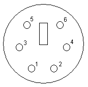
Pin Assignment (cable view)
For example, here is the signal cable for the UCI:

The UCI end of the cable is equipped with a Mini-DIN connector. The pin assignment is as follows:
|
Instrument |
|
UCI |
|
Rose or orange (Analog High) |
---------------- |
1 |
|
Gray or light blue (Analog Low) |
---------------- |
2 |
|
Green (Digital GND) |
---------------- |
3 |
|
Yellow (Digital Input) |
---------------- |
4 |
|
Brown (Digital Output) |
---------------- |
5 |
|
White (Digital Output (GND)) |
---------------- |
6 |
|
Black (Shield) |
---------------- |
Ground |
For information about the pin assignments of the other devices, refer to the respective instrument manual.
Use Signal Cable P/N 6074.0001 for the Following Instruments:
![]() Dionex UltiMate 3000 Series Variable Wavelength Detector
Dionex UltiMate 3000 Series Variable Wavelength Detector
![]() Dionex ICS-Series Variable Wavelength Detector
Dionex ICS-Series Variable Wavelength Detector
Pin Assignment (cable view)
The signal cable below shows the pin assignment for the UltiMate 3000 Series Variable Wavelength Detector and the ICS-Series Variable Wavelength Detector. One end of the cable has a Mini-DIN connector that connects to the digital I/O port on the detector rear panel. The other end of the cable has separate wires that connect to the external device(s):

The detector has two identical digital I/O ports (port A and port B). Signal names for port B are shown in parentheses.
The pin assignment is as follows:
|
Color |
Signal name |
Pin |
|
Red (or pink) |
Digital out 3 (4) relay |
1 |
|
Gray |
Digital in 3 (4) relay |
2 |
|
Green |
Digital in common GND for digital in 3 (4) and 1 (2) |
3 |
|
Yellow |
Digital in 1(2) plus |
5 |
|
Brown |
Digital out 1(2) plus |
6 |
|
White |
Digital out 1/3 (2/4) relay common |
8 |