Installing and Controlling Third-Party
Devices
![]() Agilent 7673 Autosampler on the HP 5890 GC Using the HP 18594 Controller
Box
Agilent 7673 Autosampler on the HP 5890 GC Using the HP 18594 Controller
Box
The following hardware is required to control the 7673 GC autosampler:
From Agilent:
|
Agilent part no.: 18594-60080 |
|
18594-80305 or higher |
The firmware is on the controller card (see below, not on the RS-232-C-C card). For information about the firmware version, refer to the label on the EPROM on the controller card. |
|
|
Agilent
part no.: 18594-60110 or |
|
Agilent part no.: 18594-60075 |
(The installation described below presumes that a Tray + Tray-Card is already installed.) |
|
From Dionex:
RS-232 cable (Null
Modem Cable):
DX part no.: 8914.0103A (25-pin - 9-pin, not 9-pin - 9-pin!)
Installation
The 7673 autosampler, which is part of the HP 5890 gas chromatograph, includes a controller (controller box and cards), a sample tray, and an injection unit with two injectors. Although the injection unit has its own turret, the sample tray is required for larger number of samples. Therefore, Chromeleon currently supports this instrument only with the tray.
For operating the autosampler, first install the RS-232-C card (Agilent part no.: 18594-60080) in the controller box.
Install the card in the COMM slot. Configure the card via the W1 baud rate jumper (transfer rate: 9.6 K).
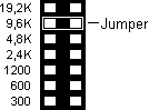
![]() Tip:
Tip:
If the card is already installed, open the controller box enclosure and then set the jumper.
Finally, install a controller card (also, refer to the Installing the Controller chapter in the HP 7673 Automatic Sampler Operating Manual). Select either the HPIB card (18594-60110) or the stand-alone controller card (Agilent part no. 18594-60060).
The HPIB-controller supports HPIB and RS-232 communication. For Chromeleon, only RS-232 communication is used.
The communication parameters are as follows: 7 Data Bits, Parity Even, 1 Stop Bit. Set these parameters via the DIP switches on the HPIB board:
DIP-Switch |
1 |
2 |
3 |
4 |
5 |
|
|
16 |
8 |
4 |
2 |
1 |
(Description on the HPIB board) |
Setting |
0 |
1 |
0 |
0 |
0 |
|
Value |
Off |
On |
Off |
Off |
Off |
|
![]() Tip:
Tip:
If the card is already installed, you can select these settings on the rear panel of the controller box.
On the rear panel, the stand-alone controller is fitted with a (9-pin) SUB-D connector labeled Test. Verify that the firmware is version 18594-80305 or higher. The corresponding EPROM is shipped with the serial interface card (18594-60080).
Connecting the Cables
Connect the injector and the controller box using the appropriate Agilent connecting cable.
Connect the sample tray to the tray card.
Use a null modem cable (25-pin to 9-pin; Dionex part no. 8914.0103A) to connect the RS-232 output of the RS-232 card to the serial interface on the server PC.
Connect the 25-pin end to the RS-232 output of the controller box.
Connect
the 9-pin connector of the null modem cable with the serial COM port
on the PC or on the UCI Universal Chromatography Interface. (Note:
If the PC is fitted with a 25-pin COM port, e.g., if a Meilhaus card
is installed in the PC, you need an appropriate adapter cable. For
more information about Meilhaus cards available from Thermo Scientific
Dionex , refer to ![]() Installing the Serial RS-232 Interface
Card (Meilhaus)..
Installing the Serial RS-232 Interface
Card (Meilhaus)..
![]() Tip:
Tip:
Please check whether the sampler is connected to an HP 5890 GC. In this case, remove the AGP remote cable.
Dionex Device Driver
Add the autosampler to the timebase. Select Add Device on the Edit or context menu, and then select Agilent (or HP) from the Manufacturers list box and 7673A GC Autosampler from the Devices list box.
Determine the controller card (stand-alone or HPIB) to be used for controlling the 7673 autosampler. You can recognize the stand-alone card by the test connector and the HPIB card by the HPIB connector protected by a red cover when unused.
Also, define the injection system of the (front-/rear injector), the syringe size, and the injector inlet.
![]() Tip:
Tip:
If two injectors are installed, the dual
inject option is enabled automatically. Both injectors can then inject
simultaneously from two different sample positions. For more information,
refer to Practical Tips for Device Control
![]() Injecting Two GC Samples Simultaneously
(7673 and 7683 Autosamplers) in the User
Help section.
Injecting Two GC Samples Simultaneously
(7673 and 7683 Autosamplers) in the User
Help section.
For detailed installation instructions, refer to the manual for the instrument.
For information about how to install the 7673
autosampler in the Server Configuration, refer to ![]() Agilent 7673 and HP7683 Autosamplers: Server
Configuration.
Agilent 7673 and HP7683 Autosamplers: Server
Configuration.
For a flow chart regarding the different HP
autosamplers, refer to ![]() Agilent GC Autosampler: Flow Chart.
Agilent GC Autosampler: Flow Chart.
For information about how to install a 7673
autosampler using the new HP G1512
controller box at the HP 5890 GC, refer to ![]() Agilent 7673 Autosampler on the HP 5890
GC Using the HP G1512 Controller Box.
Agilent 7673 Autosampler on the HP 5890
GC Using the HP G1512 Controller Box.
For installing the 7673 or 7683 autosampler
on the 6890 GC, refer to ![]() Agilent 7673 or 7683 Autosampler on the
6890 GC.
Agilent 7673 or 7683 Autosampler on the
6890 GC.
For information about how to install the dual
inject option, refer to ![]() Agilent 7673 and 7683 Autosamplers: Dual
Inject.
Agilent 7673 and 7683 Autosamplers: Dual
Inject.
Installation instructions are also available for the following Agilent devices:
HPLC Systems
![]() Agilent
HP 1050 HPLC System
Agilent
HP 1050 HPLC System
![]() Agilent
1100 HPLC System
Agilent
1100 HPLC System
![]() Agilent 1200 HPLC System
Agilent 1200 HPLC System
Gas Chromatographs
![]() Agilent
HP 5890 GC
Agilent
HP 5890 GC
![]() Agilent
6890 GC
Agilent
6890 GC