Installing and Controlling Thermo
Scientific Devices
![]() TRACE 1300 Series GC: Installation
TRACE 1300 Series GC: Installation
Device Type |
Gas chromatograph |
Device Driver: |
Thermo Scientific: TRACE 1300 Series
Driver |
Supported Hardware Options: |
|
Other Supported Options: |
|
The following options are not supported:
|
What is required?
License: |
|
Connection: |
A free Ethernet (LAN) port and the following components are required: - Ethernet LAN cable to connect the GC to the Instrument Controller PC. - Cable to connect the GC to the autosampler for hardware synchronization, depending on the autosampler type. For information, refer to the operating instructions for the autosampler.
It is
recommended to use a separate Ethernet interface for communication
with the instrument. This means that the instrument PC has two
Ethernet cards, one for the office LAN and one for communication
with the instrument. Ensure that the entered port number (default 2551)matches the configured port number on the GC. Otherwise the driver will not be able to create a connection to the GC. |
Hardware |
Hardware synchronization between the GC and the connected autosamplers. Depending on the sampler, a different cable has to be used. For detailed information about handshake settings., refer to the GC operating instructions. |
Firewall settings: |
If
a program or port is missing, make sure that the port for incoming
connections is added to the exception list in the Windows Firewall
settings. The port is set to 2551 by default. Also, see section
Connection
above. |
Hardware Installation
Device Connection: |
In order to connect an autosampler, use the appropriate cable for the respective autosampler. (For information about which cable is required, refer to the autosampler manual.) |
Device Settings: |
The communication settings must be as follows: static IP address (the IP address can be set via the front panel).
Using DHCP for address retrieval of the GC is not supported. |
PrepRun Timeout |
The GC can be started only when it is in Ready To Inject mode. Therefore, select a PrepRun Timeout that is long enough so that the injection takes place within this time. The PrepRun Timeout can be set via the GC's keypad [Config] [Oven] [PR Timeout]. For information about special module settings, refer to the installation instructions provided with the GC. |
Analog Output Interface Settings |
Analog Output Interface (AOI) settings need to be configured by means of the GC's keypad. To do so, associate an analog output channel with a detector and configure the gain range of the AOI channels. For details, refer to the installation instructions provided with the GC. For more information about setting
up timed events during the prep-run or run time phases, refer
to |
Software Installation
In the Chromeleon Server
Configuration, add the Driver
to a timebase. For details, see ![]() Adding, Configuring or Deleting Devices.
After you added the driver to the timebase, the Configuration dialog
or wizard opens automatically.
Adding, Configuring or Deleting Devices.
After you added the driver to the timebase, the Configuration dialog
or wizard opens automatically.
Enter the IP address of the GC and click the 'Get' button to automatically read the instrument configuration.
Alternatively, select the desired settings on each configuration tab page. For information about the settings on a page, click the Help button on a page or press F1.
Configuration of a Remote Inject Device
When performing injections using an external sampler that is not controlled by Chromeleon or when doing manual injections, a Remote Inject device has to be installed on the timebase (Note: The TRACE 1300 Series GC Driver must be installed on the timebase prior to the Remote Inject driver):
In the Server Configuration program, add a Remote Inject driver to the timebase. (Select Add Device on the Edit or context menu, and then select Generic from the Manufacturers list box and Remote Inject from the Devices list box.)
A dialog box for
the Remote Inject device appears. On the General
tab page, the default device name is InjectValve. You can accept the
default name or enter a different one.
From the Inject Port drop-down
list, select the inject port of the TRACE 1300 Series GC Driver (TRACE_1300.Run1
for the front inlet or TRACE_1300.Run2 for the back inlet) to which
the sampler is connected.
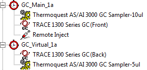
Configuration of two AS/AI 1310/3000 GC Samplers plus Remote Inject to allow Manual Injection
The following
example illustrates the configuration of two AS/AI 1310/3000 GC Samplers
with one TRACE 1300 Series GC using two timebases (timebase sharing) for
manual injection (For more information about timebase sharing, refer to
![]() Thermo Scientific TRACE 1300 Series GC: Dual Operation).
Proceed as described above:
Thermo Scientific TRACE 1300 Series GC: Dual Operation).
Proceed as described above:
If two AS/AI 1310/3000 GC Samplers are configured, you have to select an inject port of the TRACE 1300 Series Driver (TRACE_1300.Run1 for the front inlet or TRACE_1300.Run2 for the back inlet) for each autosampler to establish a connection.
Add a Remote Inject driver to the preferred timebase (front or back) and select one of the remaining inject ports of the TRACE 1300 Series Driver (TRACE_1300.Run3 for the front inlet or TRACE_1300.Run4 for the back inlet).
The configuration could look as follows:
Instrument Method Setup Using a GSV Inlet
A Program for a TRACE 1300 GC with a GSV (Gas Sampling Valve) inlet will not properly trigger the start of the run without some special modification.
Before setting up a program for the TRACE 1300 Series GC with a GSV, a Remote Inject device driver has to be installed in the device tree.
![]() Note:
Note:
The TRACE 1300 Series driver must be installed on the timebase prior to the installation of the Remote Inject driver.
For more information about the installation of a Remote Inject driver, see Configuration of a Remote Inject Device above.
Setting up a program for a TRACE 1300 GC with
a GSV requires some special modification of the program. For more information,
refer to ![]() Thermo Scientific
TRACE 1300 Series GC: Program Setup with GSV Inlet.
Thermo Scientific
TRACE 1300 Series GC: Program Setup with GSV Inlet.
Leak Check Control
You can detect gas leaks from an inlet using the Leak Check functionality in Chromeleon. When you perform a leak check, the GC measures the column flow with a true mass flow sensor and compares it to a calculated flow value obtained from the original column constant to see if the numbers match. The instrument detects a gas leak if there is a significant difference between the two values.
![]() Note:
Note:
With a TRACE 1310 GC, you can also perform a leak check using the front panel of the GC. Refer to the TRACE 1310 Hardware Manual for details.
To perform a leak check using Chromeleon
![]() Note:
Note:
This procedure requires use of the following:
The column-flowmeter connector. Refer to the TRACE 1300/1310 Hardware Manual for details.
Chromeleon's LeakCheck commands, which are available for
the GC FrontColumn/BackColumn
in the Commands dialog box (see ![]() Commands).
To open the Commands dialog box from a control panel, select
Commands on the Control
menu, or press F8.
Commands).
To open the Commands dialog box from a control panel, select
Commands on the Control
menu, or press F8.
Before starting a leak check, make sure there is a gas flow through the inlet. For example, in the Commands dialog box, set the FlowMode to PressureCtrl, set the PressureCtrl to On, and specify a nominal pressure value: Pressure.Nominal.
Use the following commands to set up the leak check:
LeakCheckPressureSet – Set the pressure for the leak check.
AllowedPressureDrop – Set a value by which the pressure is allowed to drop and still be considered to pass. Note that the available range depends on the setting for LeakCheckPressureSet.
LeakCheckTimeout – Set the duration of the leak check test.
Use the following command to start the leak check:
LeakCheckCtrl
Use the following commands to monitor the leak check:
LeakCheckElapsedTime – Reports the elapsed time for the leak check.
LeakCheckRemainingTime – Reports the remaining time for the leak check.
Finally, use the following command to see the result of the leak check:
LeakCheckStatus – Reports the status of the leak check.
When the leak check is started, the system is automatically pressurized with carrier gas and sealed to perform a leak check. At the end of the leak check, if the system is free of leaks, the Leak Check Passed message is displayed. If any leaks are found, an error message is displayed; in this case, eliminate the leaks and repeat the leak check procedure.
![]() Note:
Note:
Only a previous Column Characterization, performed under leak-free conditions, can ensure the validity of the subsequent leak check responses.
You cannot start a leak check while a leak check or a column evaluation is already running on the same or another column.
Further Information
For detailed installation instructions, refer to the operating instructions for the instrument.
For an overview of the different Thermo Scientific/Thermo
Finnigan/ThermoQuest/TSP instruments for which device drivers are available
in Chromeleon, refer to ![]() Thermo Scientific.
Thermo Scientific.
